Layout Progress


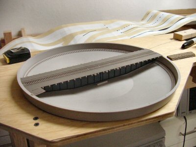
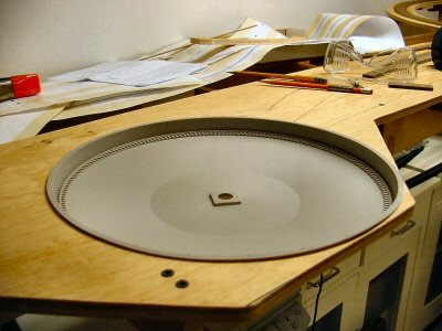
As I left off last time I had decided to buy a Walthers 90’ turntable instead of scratchbuilding.

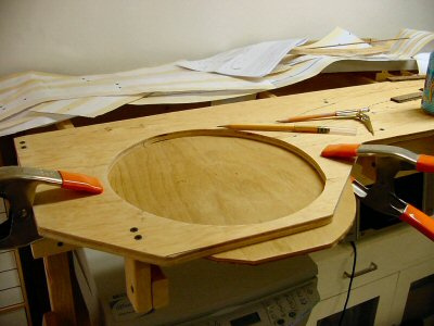
Placing it into the rough cut 11” hole I had already cut, it was clearly going to need a bigger (and more perfectly circular!) hole.

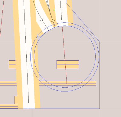
The Walther’s turntable needs a 12-1/2” diameter hole. On my trackplan I superimposed that size hole where I had the smaller hole and it was a tight fit, but it did fit.

It is a good idea to read the instructions: closer reading reveals that the turntable needs a 12-5/8” hole. As usual – everything ends up taking a bit more space than you initially plan.


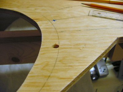
First I needed to draw a really accurate circle on the plywood. Normally this is no big deal but there’s a hole in the plywood where the center needs to be so I clamp a piece of ¼” plywood over the hole from below.

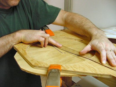
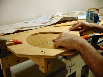
Next I need to mark the center of the circle. The approach tracks to the turntable are already laid out and their centerlines should cross exactly at the center of the circle. Using a flexible clear plastic ruler I draw lines out and where they cross will be the center of the new enlarged hole.

Drawing the first line.

Drawing the second line. Where it crosses the first is the center for the new hole.

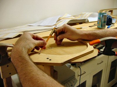
From the center just marked I use an inexpensive compass and a sharp pencil set for a 6-5/16” radius to gently mark out the new circle’s outline. This kind of compass works fine as long as you use very little force.

Drill a starter hole for the saber saw.

Cut the hole

Somehow I forgot to take any photos of this step. Maybe it was because I was holding the saw with both hands!

Anyway, I carefully cut the hole with a new blade in the saber saw and with a little bit of shaving the new hole works great.

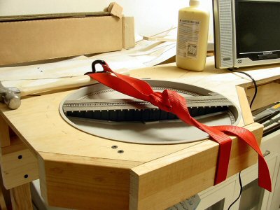
The edge of my plywood base for the yard area is now dangerously close to the edge of the turntable so I immediately add some pine 1×3 facing boards and use a cargo strap to hold them while I glue and screw them in place.

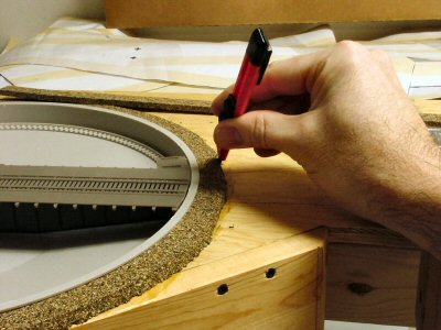
The plastic lip of the turntable is exactly the same thickness as the ties under my track. Since my track is riding on cork roadbed I need to raise the turntable to match the track height. The easy way to do this is to run a ring of roadbed around the turntable hole to use it as a riser. Then I just cut away the bevel where the approach tracks come in.


I still have to actually assemble the turntable but I’m moving on to laying the track first.

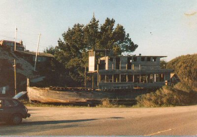
When I was younger I used to go climb and play on this little ship. Many years later (around 1982) I got a picture of it. Unfortunately, I only had a cheapo camera and the boat has since collapsed.

The SS Marin

I found the print (only 3×5 inches) and scanned it at 300 dpi optical about ten years ago. I’ve always thought she’d make a great model for a RR/Wharf scene.  

I’ve never been able to find any reference to her but she had “MARIN” faintly painted on her bow.

I think the Marin worked as a small freight and passenger ship. The main deck was very heavy construction: three layers of 2″ planking at skewed angles with asphalt and fine gravel coating on top. There was no evidence of any forward bulwark. In other photos of similar boats you see removable open rails on the forward deck.

It looked like cargo was loaded on and off the foredeck and stored as far back as the area under the main cabin. The part of the main deck covered by the upper cabin was open except for 3 or 4 support posts up the middle. One of these can be seen directly under the front of the wheelhouse.

The engine and hardware were long gone. There were indications that two cylindrical fuel tanks were mounted under the main deck on either side leaving room far a good size in-line gas/diesel engine mounted above the keel, towards the stern. She had a single screw and rudder.

There was only four feet of headroom inside the flat-bottomed hull between the frames and the deck beams under the main deck. I think she was built as a motor-boat (not converted from steam) since boilers usually had to be in the middle of the hull and there really wasn’t head room on the MARIN below the main deck.

The wheelhouse was elevated about three feet above the upper deck level. Inside, the wheelhouse had a large “shelf” across the after portion which was actually the roof of the Skipper’s cabin. The upper cabin had a small captain’s cabin forward that went full width. The remainder was undivided and had benches along the walls facing inwards.

The boat used to be about 100 feet from the water on the north shore of Bodega Bay, California. The location at Mapquest (or other map website) may be found by entering the following location: Bay Flat Rd & Whaleship Rd, Bodega Bay, CA 94923

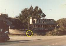
Measurements: The yellow circle shows where I placed a story pole on the ship to aid in measuring it from the photo. It was painted white and black on the belt rail of the hull, just forward of directly below the front of the wheelhouse. It is marked in feet with the first and third feet white and the middle foot black. The middle foot also has six inches marked in alternate white/black patches (these are slightly below the resolution of the camera).

I estimate the length to be about 60 feet, beam almost 20 feet.

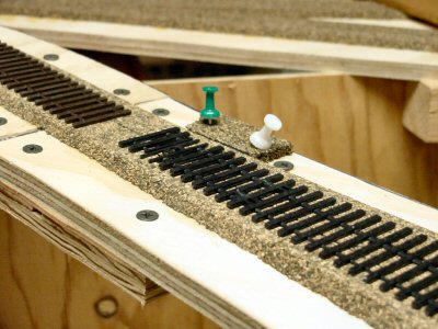
Ok, so far this first turnout is kicking my ass. I’ll produce a real “how to build these turnouts” article — when I really know to build one of these turnouts. Right now, I’m severely learning. Think of this as a “still clinging to the cliff” kind of report although I’m still having fun and I’m still happy about choosing the Central Valley turnout kits.

Central Valley Model Works (CVMW) has been around since the late 1940’s. However, their CVT system of styrene tie strips and turnout kits is relatively new. I’m building most of my track using Micro Engineering code 83 flex track. Code 83 you say? Yes, I have some old Rivarrosi and IHC engines that I actually like, and code 70 is too low for their (way too big) flanges so code 83 it is – good enough.

For turnouts I originally intended to use Walthers/Shinohara code 83 #4’s – these are excellent turnouts but were completely out of stock for the foreseeable future during the end of 2005 when I was putting all my materials together. I procrastinate enough at the best of times and having any real excuse to stop forward progress is simply too risky so I shopped around for an immediately available alternative. The CVT turnouts had been on my short list and they were available. I ordered straight from CVMW and they arrived quickly.

The pros, cons, and costs of the CVT turnouts are obvious:

Pro: great detail – museum quality looks.
Con: you need to build them yourself and I feel it’s fair to say that they are one notch more difficult than the normal way one would scratch build a turnout and obviously way more work than a pre-built turnout.
Cost: very comparable with other turnouts. Not really a factor in the decision.

I picked a spot on my layout to lay the first turnout.

An easily accessible simple siding on the mainline. The CVT instructions (yes, I actually read them) say to start by gluing down the tie strip onto the layout. However since this was my first one I chose to do a quite a bit of dry fitting on the workbench before doing anything on the layout.

I made a drilling template out of ¼ masonite and drilled the “throw” hole and holes for feeder wires. Then glued the tie block down with contact cement and glued down a small piece of roadbed to be the foundation for the switch stand.

I’d love to say “then I just attached the rails and away we go” but there has been a lot of learning. Central Valley recommends barge cement diluted with MEK to attach the rails. I tried it and this is a really good recommendation — but there is still some art involved.

After some work I got my first turnout installed and working.

I’m using Tortoise switch machines and I’m using 1/16” square brass rod to throw the turnout.

During initial track planning I specified an 80′ turntable at Tiburbon. Eighty feet looked long enough given the types of engines I wanted to run. This worked out to 11 inches in diameter and this felt ok given the overall size of the scene.

The plan was to scratchbuild the turntable but those of you who have done this before know: it’s really easy to build a turntable badly. Fortunately, I realized this immediatly after casually cutting a rough 11 inch diameter hole in the main track sheet of Tiburbon.

First: a rough hole will not do the job.

Second: it became clear that a precisely built and aligned pit, bridge, and approach tracks are required or I will be very sorry indeed.

Third: since this turntable is in the IMMEDIATE foreground of the scene it must be tidy looking.

Enter the Walthers 90′ Turntable kit (unpowered) on sale for $31.98.

I’ve had spotty to poor experiences with Walthers plastic kits but I figured for $32 I’d get at least a few pieces I could use. So far it looks great. Simple and tidy. With some easy modifications will turn smoothly. I plan on turning by hand since the table is right at the edge (will I regret this?).  

I’ll have to enlarge the existing hole but it basically fits and now I can turn a USRA 2-8-2 Mikado if I want. I’ll post details on cutting and installation soon.

Yes, actual construction! I’m breaking from the ranks of arm-chair modelers where I have been comfortably hiding (and yet still whining) for many years.

As soon as I finalized my trackplan I built a planning model to confirm I liked the track alignment and arrangement. Now I was ready to start actually building benchwork.

One of the benefits of using a CAD system like 3rd PlanIt to design your layout is that it gives you a list of which materials needed and how much of each. Exporting this data I had:

L Girder, 1×4 = 489
Wood, 1×2 = 1635
Wood, 2×2 = 843

Where these last numbers are amount needed in inches. Converting to feet and then figuring out how many 8, 10, or 12 foot pieces I needed, I was able to make one trip to the lumber yard. Okay, one and a half trips because I oops’d at one point and did not leave myself enough long pieces so I had to run back and buy a couple extra 1x4’s.

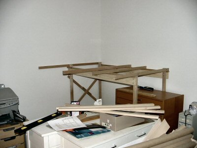
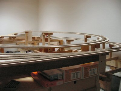
Benchwork with track.
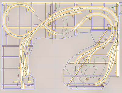
Benchwork without roadbed and track.
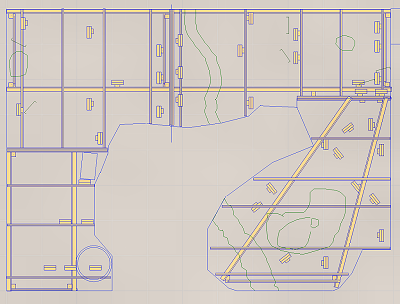
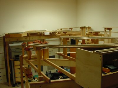
I’m building the layout into four big pieces. This is part of my plan to make the layout movable (but not necessarily easily portable).

It is important to get the first piece lined up well because it is much faster and easier going forward if you can just use the first section as your solid reference. Another decision I made was to build only the first section as a free-standing four legged section. All the other sections would have one end held up by its neighbor and the other end held up by its own legs. This minimized the number of legs needed and increased the amount of clear space below.

I built up the L-girders and cut all the legs and joists to length outdoors in advance, measuring from the CAD drawings.

Believe it or not, I live in an apartment. Let that sink in a second. An apartment. Not only do I live in an apartment, but my wife and I are spectacular pack rats. We have STUFF. My son has stuff too.

Therefore, one thing you will see in these pictures is that I could not actually start with an empty room. There was nowhere to put the stuff. An important factor in my design was that as I build a section, I move stuff under that section, clearing space to build the next section. That under-layout storage is important and was another motivation to have a rather high 53.5 inch track-zero height. I did have to fill the hallway and the living room with some displaced stuff over the one month it took to build the benchwork.

My son thought the whole thing was great. And yes, my wife is a saint.

Here’s the first section going up.
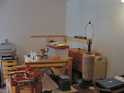
Once the first section was up it’s ready to hold up the next. I put ¼ inch lag screws on the ends of all the legs to allow the height to be adjustable for any irregularities in the floor.

Here’s the next section and as you can see I’ve already snuggled a bunch of stuff underneath. Note everything is on wheels so it’s pretty easy to pull stuff out if I need to get underneath.
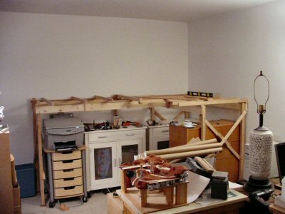
Continuing on with the third section. The sections are attached to each other only along facing 1×2 face plates at the section edges.
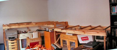
It finally dawned on me that I need more light in this already effectively windowless room. I bought a couple fixtures and put decent (relatively expensive) “full spectrum” tubes in them. I’m surface mounting everything since it all has to come out some day. I’ve tidied up the cords much better since this photo.
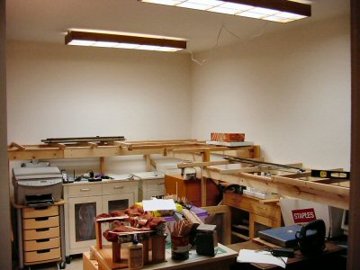

Note: this is just a start on the light. Fluorescents are an efficient way to get the bulk of the light into the space. I plan on adding many small halogen spots to give good shadows and a warmer color.

Last section.

In several of these last shots you can see that I’m using an image stitching program to combine shots giving a wider-angle view.
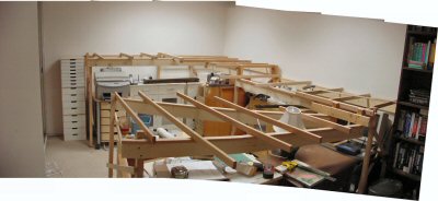
Roadway – note I use the term “roadway” to refer to the wood structure beneath the roadbed where “roadbed” is the stuff you actually put track DIRECTLY on. Some people say “sub-roadbed” — I use ½” plywood.

Building the roadway is one of those things that is REALLY hard without two things: the CAD system printing out full size paper templates and a saber saw. As far as I’m concerned there’s no other way to do it.

I actually made a paper model of the pieces of roadway to estimate how many sheets of plywood I’d need (three 4’ x 4’ sheets). By the by, unless you need several REALLY long runs, having the lumber yard cut 4×8 sheets of plywood into 4×4 sheets makes your life MUCH easier.

Anyhow, I printed out the full size templates from the CAD system (lovingly assembled from many 8-1/2 x 11 sheets of paper) and staple them to the plywood. I just staple them on long enough to copy their outline onto the wood using a nice new black sharpie pen. You can use a pencil if you want but the thick black ink line is easier to follow while cutting.
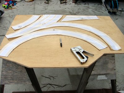
SAVE the templates: you will use them again later.

I don’t have any photos of actually cutting the plywood. It was threatening rain that weekend so I was hustling along fast enough to get it done yet still keep all my fingers. Besides the saber saw I also use a band saw whenever the shape of the piece is such that it fits through the throat of the saw.

Remember I said keep the templates? You need them to quickly and easily lay out the turnouts and the track locations. Once the roadway was installed, I would tack the templates over the pieces and use one of my trusty sharpies to trace slowly over the track plan, letting the ink soak through and mark the wood.
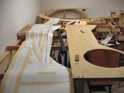
I was moving fast and the benchwork is definitely good enough but one thing I would change next time: Malcolm used 1×2 risers on his San Juan Central so I figured I would too. Next time: use 1×4 risers. The 1x2’s are plenty strong but because the 2 inches is so narrow (really 1-1/2 inches) they tend to be wobbly. For a small weight penalty, 1x4’s would have been much better.
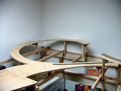
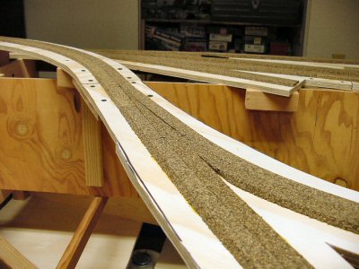
Cork Roadbed

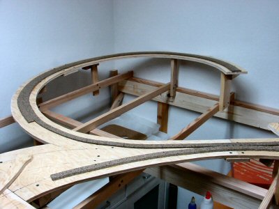
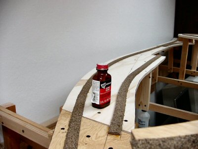
It’s fast, relatively cheap, not too messy, and it’s good enough. If I was hand laying track I might have gone for Homasote but I just didn’t want to do it that way. Frankly, the old Tru-scale milled pine roadbed was pretty good. Now available from Trout Creek Engineering — the flat stuff you put your own ties on, not the stuff they made with ties and grooves cut into it. I’d probably do something like that before Homasote. Call me weird. The only thing halfway interesting about putting down the cork is that I would use contact cement alternatively with white glue to hold it down.
This stage of layout design borrows heavily from architecture and theater. Indeed, examining the definitions of these words you get:

Architecture: The art and science of designing and erecting buildings.

Theater: (the most appropriate of the many definitions) A place that is the setting for dramatic events.

For me these definitions exactly span what model railroad design and construction is and combining them gives a good working definition of model railroading:


Model Railroading: The art and science of designing and erecting a place that is a miniature setting for dramatic events involving trains, terrain, and associated human activities.


When is it the right time to build a planning model? Really, whenever you get a point where you feel you need to “see” things better to proceed deeper.

As I mentioned before I used the 3rd PlanIt CAD program to design my trackplan. While 3rd PlanIt has decent terrain design and 3-D visualization capability, I found it would take me a very long time to use it to design the terrain of my layout so I used the CAD program to design just the track plan and benchwork plan. I decided to use a planning model to work out the way hills, valleys, and streams would work out on the plan.
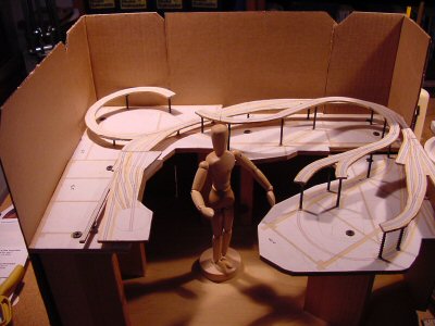
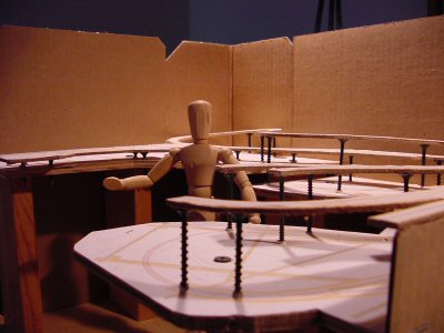
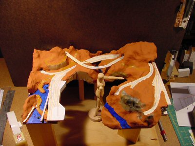
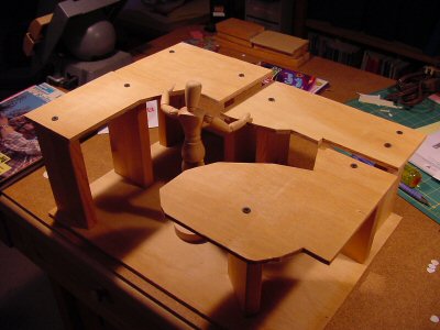
I chose a large scale: 1:8 to use for the model. This means 1/8” = 1″ (1.5 inches = 1 foot). I happen to have an artists model figure which is about 5 feet 6 inches in height in this scale.


Using the CAD program and my printer I made patterns from cardstock (manila folder paper) and transferred the shaped to ¼” plywood which I cut out with a jigsaw. The ¼” thickness is not important – it’s just what I had lying around in scrap. I used some 1 x 3’s as pedestals to set the scale height of the sections.

As you can see from the photos I broke the layout up into four sections. While the layout is not portable, it needs to be moveable. The height of each section is defined by the lowest terrain planned in that area. I followed to basic height/depth plan Furlow used for his San Juan Central but offset everything higher for my track zero height of 53.5 inches from the floor.


I glued a scale printout of the trackplan onto a sheet of 1/8” plywood and cut the plan out cookie-cutter style out of the thin plywood (this simulated the roadbed roadway I would eventually make for real out of ½” plywood). Then I glued a printout of the trackplan onto the layout sections and used wood screws as risers for the roadbed.


At the time I was worried I had done everything accurately enough. Comparing the model above to the current state of the layout it looks really close.


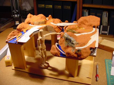
To actually model the scenery I used Sculpey (http://www.sculpey.com/) which is modeling clay that can be adjusted and shaped indefinitely and then hardened by baking in an oven (275 degrees and 15 minutes per ¼” depth). My model is big but fit nicely in our oven.

I used balls of aluminum foil to create the basic hill shapes and then covered the foil with a skin of Sculpey. Later I used acrylic paint to indicate areas that would be roads and water.


The completed model

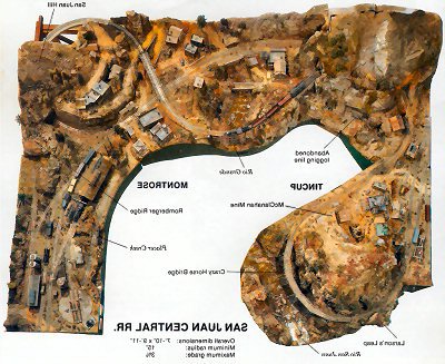
Malcolm Furlow’s San Juan Central (SJC) flipped right-left so it matches the basic configuration.

In general I followed the terrain of the SJC since I really liked the SJC looked.

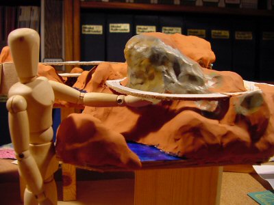
Here I have the figure pointing to the Crazy Horse Bridge.


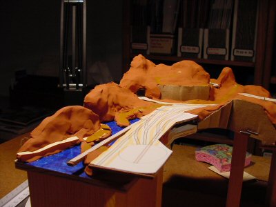
Tiburbon (a play on the name of the real town of Tiburon, California).


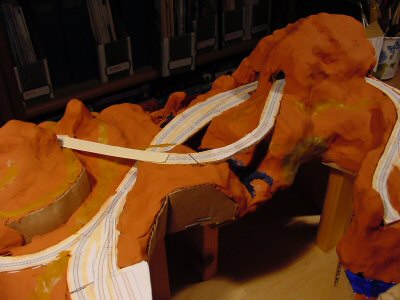
The back of the layout and the Two Tunnels area.

Between this planning model and the CAD track plan I had worked out enough of the details to proceed with construction of my layout. I really found this step a lot of fun and while I feel it is a required step to building a layout I could see building a few of these for fun just to try out different ideas for layout design.

WOW. This is a gorgeous and effective tool.

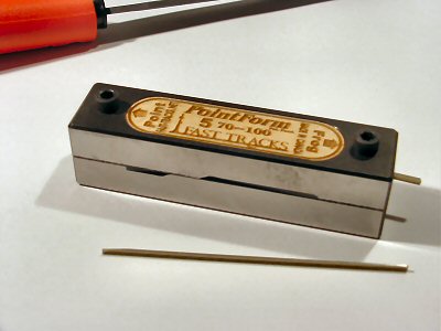
I saw a blurb about Fast Tracks products in Model Railroader and thought I’d take a look. I’m using Central Valley Model Works CVT Turnouts which require a lot of hand assembly and you have to file rails to shape for the frogs. I was worried about this so I was looking for something to make good repeatable frog rails.

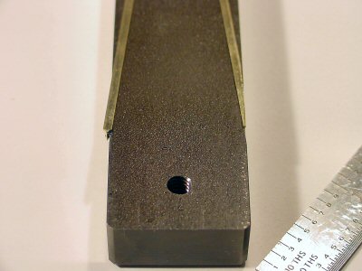
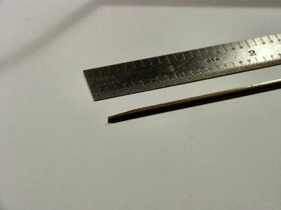
Fast Tracks makes a complete line of track building and especially turnout building tools for hand laid track. I thought the PointForm Filing Jig looked good and the website has a video of how it is used. That is very cool and sold me. They are a small operation and sometimes get swamped with orders. In my case my order arrived in about three weeks.

The fit and finish of the tools are fantastic and they work perfectly the first time. Highly recommended.

I also bought their Rail Roller and I’ll describe that soon in another post.

I’m building an HO version of Malcolm Furlow’s San Juan Central as descibed in his HO Narrow Gauge Railroad You Can Build (1984).

Why that plan?

While I love narrow gauge, why HO standard guage and not HOn3 or anything n3?

The answers are driven by one main goal and an associated attitude. I decided that my goal for 2006 is to work continiously — at least 12 hours a week — on a model railroad and that in this year I must make significant overall progress on the layout. To meet this goal I have taken the following attiude: it does not have to be a perfect layout. It just has to be good enough. Significantly, I have also made a pledge to devote all my modelling energy this year (i.e., time and money) to the layout. This means forsaking my strong interests in all other types of models and model building.

For YEARS I have been saying to anyone who would listen that I wanted to build a layout. I’m finding it stunning that simply saying “good enough” suddenly gives me license to proceed. I started planning in October and November, building benchwork in December, and started roadbed in January 2006.

Coming posts will describe planning choices I made as well as progress reports on what I’m doing currently.

I am not paid for anything I write in this blog. I accept no advertising. The product reviews are based on my personal experience with items I purchased unless I say otherwise.

Copied at  The Layout Project

« Previous Page